TA的每日心情 | 开心
18 小时前 |
|---|
签到天数: 3751 天 连续签到: 77 天 [LV.Master]伴坛终老
|
|
本帖最后由 toofree 于 2017-1-19 03:22 编辑
【赚周年币】技术帖Week3-Day1——LPC824 Breakout之15、UART0、1、2
本贴测试程序,以上一贴最后上传压缩包做主工程模板。参见贴子最末尾的附件。
【赚周年币】技术帖Week2-Day7——LPC824 Breakout之14、SPI NOKIA5110https://www.cirmall.com/bbs/forum ... 63170&fromuid=17147

当然以其它之前的帖子为模板也可以,比如,【赚周年币】技术帖Week1-Day4——LPC824 Breakout之四,串口printfhttps://www.cirmall.com/bbs/forum ... 59498&fromuid=17147
但是不能再早了,因为本帖会用到修改过的“user_bsp\src\Keil_Retarget1.c”文件。之所以要以上一贴压缩包为模板,只是因为不想重新解压压缩包,而只在本人电脑原有测试模板上修改增加。
复制上一贴的“LPC824_Example_Code_Bundle_Keil_r1.0\Shared_Project_Source_Code\Example_USART1M_USART2S”工程,改名为“Example_USART1M_USART2S_TEST”,其它文件及文件夹,也相应改名。方法及注意事项,参考之前贴子。
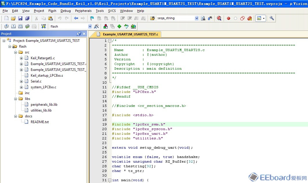
把原工程中的“Keil_Retarget.c”文件,替换为“Shared_Project_Source_Code\user_bsp\src\Keil_Retarget1.c”。把工程中程序文件中所有“\n\r”,全部改为“\r\n”,不要问为什么,地球人都知道。最后工程视图如下:

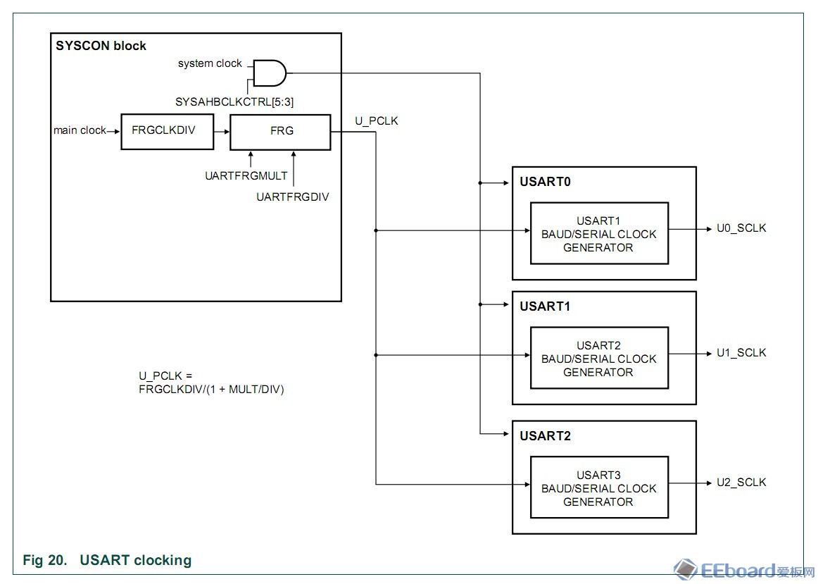
首先我们来看两个时钟框图。UM10800.pdf第184页如下图:

UM10800.pdf第30页如下图:

其中由system clock来的时钟,作为UART模块内核逻辑工程时钟;从main clock来的U_PCLK用于波特率生成。
同步模式和异步模式的波特率计算方式不同,同步模式波特是异步的16倍。异步模式是用16倍时钟来采样每一位数据的,而同步模式是在同步时钟的作用下同步采样,不需要采样误差调整。这在数据手册中有体现。

在程序中注释部分也有说明。“Serial.c”中注释如下:

“Example_USART1M_USART2S_TEST.c”中注释如下:

- // Configure the UARTCLKDIV, default for calculation below is same as AHBCLKDIV
- LPC_SYSCON->UARTCLKDIV = LPC_SYSCON->SYSAHBCLKDIV;
- // Configure the FRG (default for calculation below is divide-by-1)
- LPC_SYSCON->UARTFRGMULT = 0;
- LPC_SYSCON->UARTFRGDIV = 255;
串口0的BRG寄存器很容易算出,LPC_USART0->BRG = (SystemCoreClock / (16 * desired_baud)) - 1; BRG == (30000000 / (16*115200) - 1) == 15
串口1、2的BRG寄存器值计算,LPC_USART1->BRG = (U_PCLK/desired_baud)-1 ; BRG == (30000000 / 115200) - 1 == 259
串口0异步模式配置寄存器设置- // Configure the USART0 CFG register:
- // 8 data bits, no parity, one stop bit, no flow control, asynchronous mode
- LPC_USART0->CFG = DATA_LENG_8|PARITY_NONE|STOP_BIT_1;
- // Configure the USART1 CFG register:
- // 8 data bits, no parity, one stop bit, no flow control, synchronous mode, sample on falling edges, master mode, no loop-back
- LPC_USART1->CFG = DATA_LENG_8|PARITY_NONE|STOP_BIT_1|SYNC_EN|SYNC_MS;
在主程序中,开启了UART2接收中断。主程序中,UART1给UART2发数,UART2中断接收,UART0作为标准打印串口。UART1与UART2之间,收发管脚P0_13、P0_14相当于已经内部连接,而仅仅需要把UART1的同步串行时钟输出管脚P0_24,与UART2的串行时钟输入管脚P0_25,外部短接,即可完成UART1到UART2的数据传送。
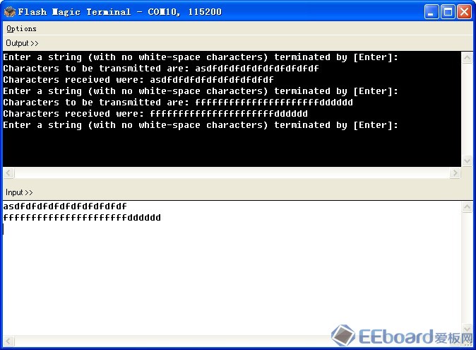
编译、下载程序、复位全速运行,在串口终端收发数据,得到预期实验结果。

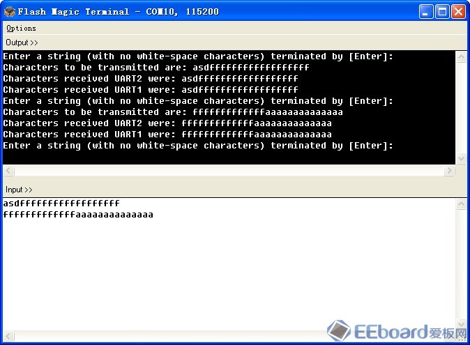
测试还没有完噢,我们照猫画虎,把UART1、UART2改为异步模式,UART1、UART2分别互相收发试试。
修改后的主程序“Example_USART1M_USART2S_TEST.c”文件- /*
- ===============================================================================
- Name : Example_USART1M_USART2S.c
- Author : $(author)
- Version :
- Copyright : $(copyright)
- Description : main definition
- ===============================================================================
- */
- //#ifdef __USE_CMSIS
- #include "LPC8xx.h"
- //#endif
- //#include <cr_section_macros.h>
- #include <stdio.h>
- #include "lpc8xx_swm.h"
- #include "lpc8xx_syscon.h"
- #include "lpc8xx_uart.h"
- #include "utilities.h"
- extern void setup_debug_uart(void);
- volatile enum {false, true} handshake1,handshake2;
- volatile unsigned char RX1_Buffer[32],RX2_Buffer[32];
- char thestring[32];
- char * tx_ptr;
- int main(void) {
- uint32_t temp;
- // Configure the debug uart (see Serial.c)
- setup_debug_uart();
- // Configure USART1 as master, USART2 as slave
- // Bit rate = 115,200 b.p.s
- // 8 data bits
- // No parity
- // 1 stop bit
- // UARTCLKDIV, FRG, and BRG calculation
- // For synchronous mode, the formula is
- // BRG + 1 = MainClk * (1/baud) * (1/(1+(frgmult/frgdiv))) * (1/UARTCLKDIV)
- // main clock = 60 MHz want baudrate = 115,200 Hz
- // Use UARTCLKDIV = divide-by-2, FRG = 1
- // Then the formula is (BRG + 1) = (main clock / 2*baudrate) = 260.4
- // So use BRG = 259
- // SWM settings for USART1 (master):
- // P0.12 = U1_SCLK
- // P0.13 = U1_TXD
- // P0.14 = U1_RXD
- //
- // SWM settings for USART2 (slave):
- // P0.15 = U2_SCLK (requires external connection from P0.12)
- // P0.13 = U2_RXD
- // P0.14 = U2_TXD
- // Enable clocks to USARTs 1, 2, SWM
- LPC_SYSCON->SYSAHBCLKCTRL |= (UART1 | UART2 | SWM);
- // Configure the SWM (see utilities_lib and lpc8xx_swm.h)
- //ConfigSWM(U1_SCLK, P0_24);
- ConfigSWM(U1_TXD, P0_13);
- ConfigSWM(U1_RXD, P0_14);
- //ConfigSWM(U2_SCLK, P0_25);
- ConfigSWM(U2_RXD, P0_13);
- ConfigSWM(U2_TXD, P0_14);
- // Configure the UARTCLKDIV
- //LPC_SYSCON->UARTCLKDIV = 2;
- // Configure the FRG
- LPC_SYSCON->UARTFRGMULT = 0;
- LPC_SYSCON->UARTFRGDIV = 255;
- // Setup USART1 ...
- // Give USART1 a reset
- LPC_SYSCON->PRESETCTRL &= (UART1_RST_N);
- LPC_SYSCON->PRESETCTRL |= ~(UART1_RST_N);
- // Configure the USART1 baud rate generator (value written to BRG divides by value+1)
- //LPC_USART1->BRG = 259;
- LPC_USART1->BRG = 15;
- // Configure the USART1 CFG register:
- // 8 data bits, no parity, one stop bit, no flow control, synchronous mode, sample on falling edges, master mode, no loop-back
- //LPC_USART1->CFG = DATA_LENG_8|PARITY_NONE|STOP_BIT_1|SYNC_EN|SYNC_MS;
- // 8 data bits, no parity, one stop bit, no flow control, asynchronous mode
- LPC_USART1->CFG = DATA_LENG_8|PARITY_NONE|STOP_BIT_1;
- // Configure the USART1 CTL register (nothing to be done here)
- // No continuous break, no address detect, no Tx disable, no CC, no CLRCC
- LPC_USART1->CTL = 0;
- // Clear any pending flags (Just to be safe, isn't necessary after the peripheral reset)
- LPC_USART1->STAT = 0xFFFF;
-
- // Enable the UART2 RX Ready Interrupt
- LPC_USART1->INTENSET = RXRDY;
- NVIC_EnableIRQ(UART1_IRQn);
- // Enable USART1
- LPC_USART1->CFG |= UART_EN;
- // Setup USART2 ...
- // Give USART2 a reset
- LPC_SYSCON->PRESETCTRL &= (UART2_RST_N);
- LPC_SYSCON->PRESETCTRL |= ~(UART2_RST_N);
- // Configure the baud rate generator (value written to BRG divides by value+1)
- //LPC_USART2->BRG = 259;
- LPC_USART2->BRG = 15;
- // Configure the USART2 CFG register:
- // 8 data bits, no parity, one stop bit, no flow control, synchronous mode, sample on falling edges, slave mode, no loop-back
- //LPC_USART2->CFG = DATA_LENG_8|PARITY_NONE|STOP_BIT_1|SYNC_EN;
- // 8 data bits, no parity, one stop bit, no flow control, asynchronous mode
- LPC_USART2->CFG = DATA_LENG_8|PARITY_NONE|STOP_BIT_1;
- // Configure the USART2 CTL register (nothing to be done here)
- // No continuous break, no address detect, no Tx disable, no CC, no CLRCC
- LPC_USART2->CTL = 0;
- // Clear any pending flags (Just to be safe, isn't necessary after the peripheral reset)
- LPC_USART2->STAT = 0xFFFF;
- // Enable the UART2 RX Ready Interrupt
- LPC_USART2->INTENSET = RXRDY;
- NVIC_EnableIRQ(UART2_IRQn);
- // Enable USART2
- LPC_USART2->CFG |= UART_EN;
- while (1) {
- GetConsoleString(thestring); // See utilities_lib
- printf("Characters to be transmitted are: %s\r\n", thestring);
- tx_ptr = &thestring[0];
- handshake1 = false;
- handshake2 = false;
- do {
- temp = *tx_ptr++;
- // Wait for TXRDY on USART1
- while (((LPC_USART1->STAT) & (1<<2)) == 0);
- // Write the current character to the USART1 TXDAT register
- LPC_USART1->TXDAT = temp;
- } while (temp != 0);
- // Wait for handshake from ISR
- while(handshake2 == false);
- // Echo the string received by USART2 back to the console
- printf("Characters received UART2 were: %s\r\n", RX2_Buffer);
-
- tx_ptr = RX2_Buffer;
- do {
- temp = *tx_ptr++;
- // Wait for TXRDY on USART2
- while (((LPC_USART2->STAT) & (1<<2)) == 0);
- // Write the current character to the USART1 TXDAT register
- LPC_USART2->TXDAT = temp;
- } while (temp != 0);
- // Wait for handshake from ISR
- while(handshake1 == false); //有错误,更正。之前为handshake2
- // Echo the string received by USART1 back to the console
- printf("Characters received UART1 were: %s\r\n", RX1_Buffer);
- } // end of while 1
- } // end of main
- /*
- * Example_USART1M_USART2S_ISR.c
- */
- #include "LPC8xx.h"
- extern volatile unsigned char RX1_Buffer[32],RX2_Buffer[32];
- extern volatile enum {false, true} handshake1,handshake2;
- static uint32_t interrupt_counter2 = 0,interrupt_counter1 = 0;
- /*****************************************************************************
- ** Function name: UART2_IRQHandler
- **
- ** Description: UART2 interrupt service routine
- **
- ** parameters: None
- ** Returned value: None
- **
- *****************************************************************************/
- void UART2_IRQHandler() {
- unsigned char temp;
- temp = LPC_USART2->RXDAT ;
- RX2_Buffer[interrupt_counter2] = temp;
- if (temp == 0) { // NULL string terminator is current character
- handshake2 = true;
- interrupt_counter2 = 0;
- }
- else {
- interrupt_counter2++;
- }
- return;
- }
- /*****************************************************************************
- ** Function name: UART2_IRQHandler
- **
- ** Description: UART2 interrupt service routine
- **
- ** parameters: None
- ** Returned value: None
- **
- *****************************************************************************/
- void UART1_IRQHandler() {
- unsigned char temp;
- temp = LPC_USART1->RXDAT ;
- RX1_Buffer[interrupt_counter1] = temp;
- if (temp == 0) { // NULL string terminator is current character
- handshake1 = true;
- interrupt_counter1 = 0;
- }
- else {
- interrupt_counter1++;
- }
- return;
- }

依照惯例, 修改后工程文件打包附上。
 LPC824_Example_Code_Bundle_Keil_r1.0(201701160146).rar
(3.36 MB, 下载次数: 38)
|
评分
-
查看全部评分
|
 /2
/2 


 发表于 2017-1-15 23:56:26


 楼主
楼主

