ModelSim仿真入门:功能仿真本实验的目的就是在ModelSim环境下学习掌握该软件的一般仿真测试流程和仿真测试方法,另外学习编写简单的Test Bench程序并在ModelSim下进行调试。
实验步骤如下:[color=rgb(34, 34, 34) !important] 1. 打开ModelSim软件,如图1所示: [color=rgb(34, 34, 34) !important]

[color=rgb(34, 34, 34) !important] 图1 打开软件 [color=rgb(34, 34, 34) !important]
[color=rgb(34, 34, 34) !important] 2. 软件的启动画面如图2所示,进入界面后如图3所示: [color=rgb(34, 34, 34) !important]

[color=rgb(34, 34, 34) !important] 图2 软件的启动画面 [color=rgb(34, 34, 34) !important]
[color=rgb(34, 34, 34) !important]
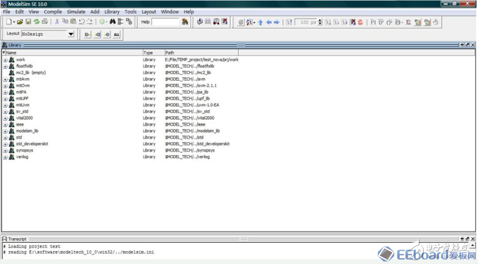
[color=rgb(34, 34, 34) !important] 图3 软件进入后的画面 [color=rgb(34, 34, 34) !important]
[color=rgb(34, 34, 34) !important]注意:如果是第一次使用软件,进入后会有一些诸如软件的欢迎画面等不相关的对话框,无须担心,直接关闭即可,亦可选择下次登陆时不显示。
[color=rgb(34, 34, 34) !important]3. 进入ModelSim主窗口后,选择File菜单下的“New→Project”,新建一个工程,在弹出的对话框中,给该工程命名并指定一个存放的路径,如图4所示: [color=rgb(34, 34, 34) !important]
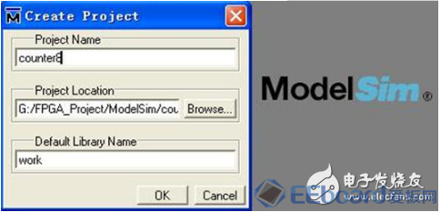
[color=rgb(34, 34, 34) !important]图4 新建工程 [color=rgb(34, 34, 34) !important]
[color=rgb(34, 34, 34) !important] 在这里,工程名和你的顶层文件名保持一致是推荐的做法。路径的注意事项已经说过,这里不再提及。默认的库名就是“work”,这个无需更改,点击“OK”即可。 [color=rgb(34, 34, 34) !important] 4. 之后会弹出如图5的对话框,选择是新建一个文件还是添加已存在的文件,这两个都可以选择,假如事先编好了文件,就选择添加进来,假如没有就新建。在这里使用添加已有文件,在软件开始之前就编好所用的程序,这样比较方便些。软件自带的编辑环境不是很好,使用第三方的编辑工具是推荐的方法。建议使用UltraEdit或Notepad++这些专业的代码编辑软件。 [color=rgb(34, 34, 34) !important] UltraEdit偏重于功能的强大和丰富的用户可定制化特性,而Notepad++更加注重易用性。两者在普通功能上差异不是特别大,根据自己的喜好选择一款即可。 [color=rgb(34, 34, 34) !important]
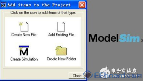
[color=rgb(34, 34, 34) !important] 图5 给工程中添加文件 [color=rgb(34, 34, 34) !important]
[color=rgb(34, 34, 34) !important]在路径G:\FPGA_Project\ModelSim\counter8下新建两个文件,一个是counter8.v,一个是test_counter8.v,前者是我们的原始的设计文件,后者是其相应的仿真测试文件。在这个路径的Windows目录下,在空白处右键选择新建一个文本文档.TXT格式,然后在这个文件上右键选择UltraEdit或Edit with Notepad++就可以启动相应的代码编辑工具进行编辑了,保存的时候注意存成“.v”或“.vhd”格式即可。 [color=rgb(34, 34, 34) !important]以下给出两个文件的代码: [color=rgb(34, 34, 34) !important]第一个文件: - //-----------------------------------------------------
- // DesignName : counter8
- // FileName : counter8.v
- //Function : 8 bits counter with asyncclear and sync load
- //Coder : Cheng xu
- //-----------------------------------------------------
- modulecounter8(
- clk ,
- aclr ,
- load ,
- load_din ,
- dout
- );
- // Portdeclarations
- input clk ;
- input aclr ;
- input load ;
- input [7:0] load_din ;
- output [7:0] dout ;
- //InternalVariables
- wire clk ;
- wire aclr ;
- wire load ;
- wire [7:0] load_din ;
- wire [7:0] dout ;
- reg [7:0] counter = 0 ;
- //CodeStarts Here
- always @(posedge clk or negedge aclr)
- if(!aclr)
- counter 《= 0;
- else if(load == 1)
- counter 《= load_din;
- else
- counter 《= counter + 1;
- assigndout = counter;
- endmodule
[color=rgb(34, 34, 34) !important]第二个文件: - //test_counter8.v
- `timescale1ns/1ns //注意最前面的符号是数字键“1”左边的//那个符号,不是单引号
- moduletest_counter8;
- reg clk ;
- reg aclr ;
- reg load ;
- reg [7:0] load_din ;
- wire [7:0] dout ;
- initial
- begin
- clk = 0;
- aclr = 1;
- load = 0;
- load_din = 0;
- #120 aclr = 0;
- #40 aclr = 1;
- #20 load = 1;
- load_din = 100;
- #20 load = 0;
- #100 $stop; //可以不添加这个仿真结束的系统任务
- end
- always#10 clk = ~clk;
- counter8U(
- .clk(clk),
- .aclr(aclr),
- .load(load),
- .load_din(load_din),
- .dout(dout)
- );
- endmodule
[color=rgb(34, 34, 34) !important] 这样,我们就在该工程路径下建立好了这两个文件。当然新建这两个文件的的工作可以是放在我们这个全部的工作开始之前进行的,无需等到第4个步骤开始的时候再进行。 [color=rgb(34, 34, 34) !important] 5. 把刚才新建的文件添加到工程中去,点击“AddExisting Flie”后出现如下画面,如图6所示:
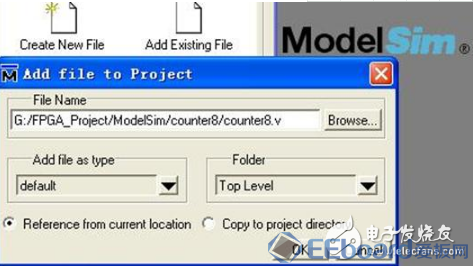
图6 添加原始的待测试程序文件
点击“OK”后,继续添加另外一个测试文件,如图7所示:

图7 添加仿真测试文件
[color=rgb(34, 34, 34) !important]之后点“OK”,再关闭“Add items to the Project”这个对话框。最简单的办法是一次同时添加两个文件,点击“Browse”之后,鼠标直接框选这两个文件,这样可以一次添加多个文件到ModelSim工程中。 [color=rgb(34, 34, 34) !important] 6. 我们在软件的Project区域已经能看到我们添加的这两个文件了,如图8所示: [color=rgb(34, 34, 34) !important]

[color=rgb(34, 34, 34) !important] 图8 Project区域状态 [color=rgb(34, 34, 34) !important]
[color=rgb(34, 34, 34) !important]我们下面就可以编译这两个文件了,这时候因为还没有编译文件,所以Status一栏显示的是两个问号。接着在这个Project区域单击鼠标右键,选择“Compile→Compile All”,把HDL源文件编译到当前工程的工作库当中去。如图9所示: [color=rgb(34, 34, 34) !important]

[color=rgb(34, 34, 34) !important] 图9 编译源文件和仿真测试文件 [color=rgb(34, 34, 34) !important]
[color=rgb(34, 34, 34) !important]我们在软件下方的Transcript区域中假如看到如图10的字样,就说明编译通过了: [color=rgb(34, 34, 34) !important]
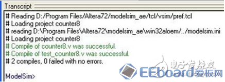
[color=rgb(34, 34, 34) !important] 图10 编译成功画面 [color=rgb(34, 34, 34) !important]
[color=rgb(34, 34, 34) !important] 注意中间的两个successful说明成功了。另外,我们在Project区域中的Status一栏中能够看见两个绿色的勾,这也是一种编译成功的提示。 [color=rgb(34, 34, 34) !important] 7. 编译通过之后,在Project区域鼠标右键点击“Add to Project → Simulation Configuration”,如图11所示: [color=rgb(34, 34, 34) !important]
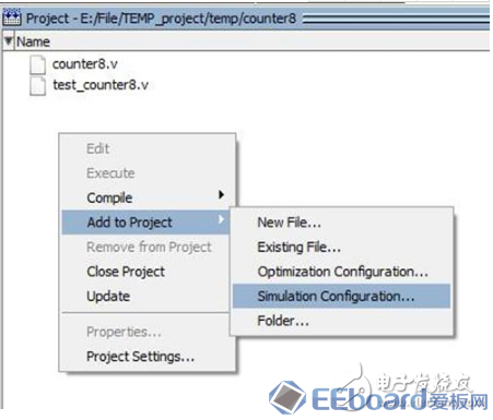
[color=rgb(34, 34, 34) !important] 图11 添加Simulation Configuration [color=rgb(34, 34, 34) !important]
[color=rgb(34, 34, 34) !important] 在出现的Add SimulationConfiguration对话框的右下角打开OptimizationOptions,打开后切换到Options选项卡页面,在Optimization Level中选择Disable Optimizations,如图12所示: [color=rgb(34, 34, 34) !important]
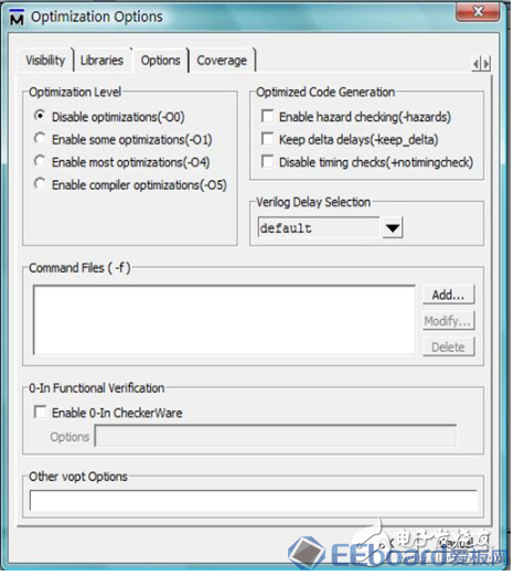
[color=rgb(34, 34, 34) !important] 图12 关闭优化选项 [color=rgb(34, 34, 34) !important]
[color=rgb(34, 34, 34) !important]点击OK确定之后返回Add Simulation Configuration对话框,在Optimization栏中关闭Enable Optimization,再展开work目录,选中Test Bench文件test_counter8,之后save保存。如图13所示: [color=rgb(34, 34, 34) !important]
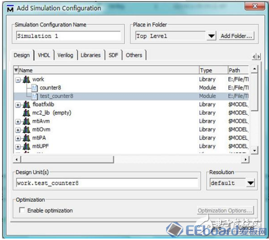
[color=rgb(34, 34, 34) !important]图13 关闭优化选项 [color=rgb(34, 34, 34) !important]
[color=rgb(34, 34, 34) !important] 此时会在Project区域出现一个仿真配置文件:Simulation 1,双击它就能进入仿真了,在重启ModelSim之后,还可以双击它进入仿真,比较方便。 [color=rgb(34, 34, 34) !important] 注意:如果不关闭优化选项的话,有时候ModelSim软件会报错导致不能正常进行仿真。 [color=rgb(34, 34, 34) !important] 8. 双击“Simulation 1”后进入仿真波形界面,在Object区域鼠标右键选择“Add → To Wave → Signals inRegion”,把待仿真的信号添加入Wave窗口。如图14所示: [color=rgb(34, 34, 34) !important]
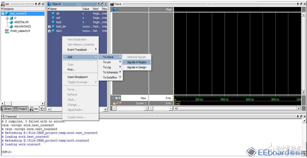
[color=rgb(34, 34, 34) !important] 图14 待仿真的信号添加入Wave窗口 [color=rgb(34, 34, 34) !important]
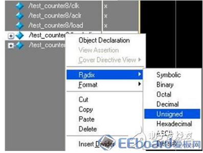
[color=rgb(34, 34, 34) !important] 9. 接着我们把wave窗口中的两个信号量改成无符号数显示,方便我们观察,在load_din和dout上依次单击鼠标右键,按照图15的方法修改即可:
ModelSim仿真入门:时序仿真[color=rgb(34, 34, 34) !important] 正如前面第二讲所述,时序仿真在实际应用中使用的并不多,但是为了保持仿真系列文档的完整性,我们还是把仿真的方法写出来。 [color=rgb(34, 34, 34) !important] 时序仿真就要比第二讲的功能仿真步骤上要多一些,本讲以目前的QuartusII的12.0SP2版本和Cyclone IV的EP4CE6F17C8为例,讲解下时序仿真的方法和步骤。 [color=rgb(34, 34, 34) !important] 时序仿真需要的文件总共有以下几种: [color=rgb(34, 34, 34) !important] ①综合后生成的网表文件“ * .vo ”(假如在Setting里面设置里输出语言为VHDL的话,则生成的网表文件为“ * .vho”) [color=rgb(34, 34, 34) !important] ②综合后生成的具有工程延时信息的文件“ * .sdo ”(VHDL语言亦为此) [color=rgb(34, 34, 34) !important] ③ Test Bench程序文件 [color=rgb(34, 34, 34) !important] ④ Altera的元器件库 [color=rgb(34, 34, 34) !important] 大致的过程就是先在Quartus II中生成网表文件和时延文件,然后调用ModelSim进行仿真,具体的时序仿真步骤如下: [color=rgb(34, 34, 34) !important] 1. 打开Quartus II软件,新建工程,再新建文件counter8.v,把上一讲中的counter8.v这个源文件复制到Quartus II的工程目录中,并添加该文件到工程中。接着,选择“Settings”→“EDA Tool Settings”,选择左栏的“Simulation”,设置情况如图1所示。 [color=rgb(34, 34, 34) !important] 第一栏的“Tool name”选择ModelSim-Altera [color=rgb(34, 34, 34) !important] 第二栏的“Format for output netlist”选择自己熟悉的语言,VHDL或Verilog都可以,后面的“output directory”是选择输出的网表文件和延时信息文件的存放路径,一般选择默认即可,这样的话,将来编译成功后,会在Quartus II的工程文件夹(本例为counter8这个文件夹)下面生成一个simulation/modelsim的文件夹,里面存有将来要用到的.vo和.sdo这两个文件。 [color=rgb(34, 34, 34) !important] 再往下,看到有“More EDA Netlist WritterSettings…”按钮,点击后进入设置画面,设置情况如图2所示。注意的地方就是Generatenetlist for functional simulation这一项后面是处于OFF的关闭状态,这样才能生成我们所要的时序仿真文件。 [color=rgb(34, 34, 34) !important]
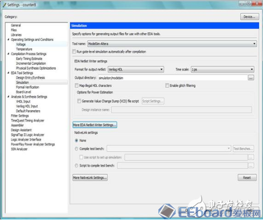
[color=rgb(34, 34, 34) !important] 图1 simulation的设置 [color=rgb(34, 34, 34) !important]
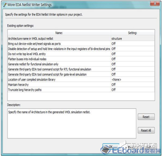
[color=rgb(34, 34, 34) !important] 图2 More EDA Netlist WritterSettings的设置 [color=rgb(34, 34, 34) !important]
[color=rgb(34, 34, 34) !important]都设置好了以后,全部点击“OK”后退出设置,在QII的编译环境下执行全编译。编译中的情况如图3所示: [color=rgb(34, 34, 34) !important]
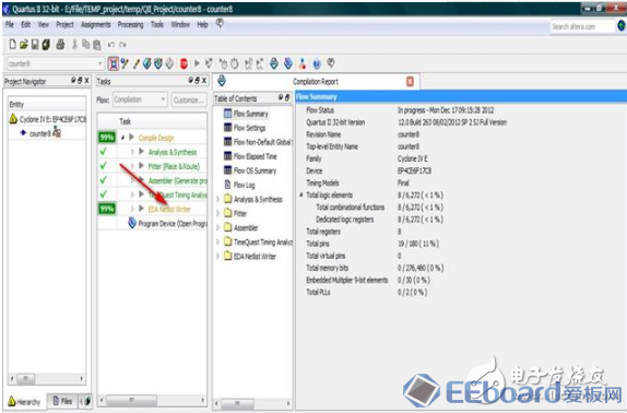
[color=rgb(34, 34, 34) !important] 图3 编译中的情况 [color=rgb(34, 34, 34) !important]
[color=rgb(34, 34, 34) !important]注意:下面比我们平时进行的全编译时多了一项“EDANetlist Writer”,图3的红色箭头指向的位置。 [color=rgb(34, 34, 34) !important] 2. 找到新建工程目录所在的文件夹,在里面找到simulation/modelsim这个文件夹,会发现文件夹内有10个文件,如图4所示: [color=rgb(34, 34, 34) !important]
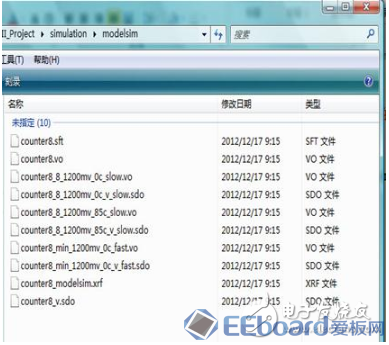
[color=rgb(34, 34, 34) !important] 图4 生成的10个文件 [color=rgb(34, 34, 34) !important]
[color=rgb(34, 34, 34) !important] 注意:counter8.vo和counter8_v.sdo就是时序仿真需要的两个重要的网表文件,它们与counter8_8_1200mv_85c_slow.vo和counter8_8_1200mv_85c_v_slow.sdo只是命名不同而已,文件的内容其实是一样的。后两个是QuartusII目前新的网表文件的命名方法,文件名标示出了速度等级(-8)、内核电压(1200mv)、温度条件(85℃)以及时序模型(slow)。 [color=rgb(34, 34, 34) !important] 之所以Altera还没有取消旧的命名文件方法并让QuartusII继续生成这两个网表文件,是因为有TclScript文件是按照旧的命名方法写的,需要兼容它们。 [color=rgb(34, 34, 34) !important] 以下时序仿真以counter8.vo和counter8_v.sdo为例,如果需要用fast时序模型做仿真,也是按照下面的方法进行,只是把vo和sdo文件换为fast。 [color=rgb(34, 34, 34) !important] 另外“.xrf”和“.sft”这两个文件,是QuartusII编译生成的一些相关的信息文件,时序仿真用不到。 [color=rgb(34, 34, 34) !important] 3. 打开ModelSim软件,新建一个工程,如图5所示: [color=rgb(34, 34, 34) !important]
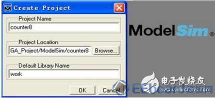
[color=rgb(34, 34, 34) !important]图5 新建工程并指定路径 [color=rgb(34, 34, 34) !important]
[color=rgb(34, 34, 34) !important] ①接着把刚才生成的counter8.vo和counter8_v.sdo两个文件拷贝到现在个仿真工程的目录下面。 [color=rgb(34, 34, 34) !important] ②之后还要拷贝一个很重要的文件,到QuartusII的安装目录下: \quartus\eda\sim_lib,找到cycloneive_atoms.v这个文件,这个是Altera器件库的库文件,进行时序仿真就是基于这个库文件的,把它也拷贝到仿真工程目录。 [color=rgb(34, 34, 34) !important] 注意:我们是以Cyclone IV的EP4CE6F17C8为例的,所以这里需要复制的就是cycloneive这个库文件,如果是其它器件的话,需要再对应选择。 [color=rgb(34, 34, 34) !important] ③把test_counter8.v文件拷贝到这个仿真工程目录下面。 [color=rgb(34, 34, 34) !important] ④在QII安装目录的。.altera\12.0\quartus\eda\fv_lib\verilog,把这里面的dffeas.v和dffep.v文件拷贝到这个仿真工程目录下面。 [color=rgb(34, 34, 34) !important] 4. 进行完上面的步骤后,返回到ModelSim这个软件界面,会发现软件还停留在刚才新建工程,需要我们为其工程添加文件的对话框,那我们就添加文件,把“counter8.vo”、“cycloneive_atoms.v”、“test_counter8.v”、“dffeas.v”和“dffep.v”这5个文件添加进去,如图6所示: [color=rgb(34, 34, 34) !important]

[color=rgb(34, 34, 34) !important] 图6 添加的5个文件 [color=rgb(34, 34, 34) !important]
[color=rgb(34, 34, 34) !important] 注意:此时不需要添加counter8.v这个文件了,.vo文件可以替代它。 [color=rgb(34, 34, 34) !important] 5. 之后关闭添加文件对话框,可以看见Project区域有了我们添加的5个文件了,在该区域点右键,“Compile”→“Compile All”执行全部编译。 [color=rgb(34, 34, 34) !important] 6. 在Project区域点右键,“Add to Project”→“Simulation Configuration”添加一个仿真配置的设置,这时会直接弹出添加仿真配置对话框,这里,我们要进行如下的设置: [color=rgb(34, 34, 34) !important] ①在“Design”选项卡下展开work前面的“+”号后点选test_counter8,这个就是Test Bench文件。如图7所示: [color=rgb(34, 34, 34) !important]
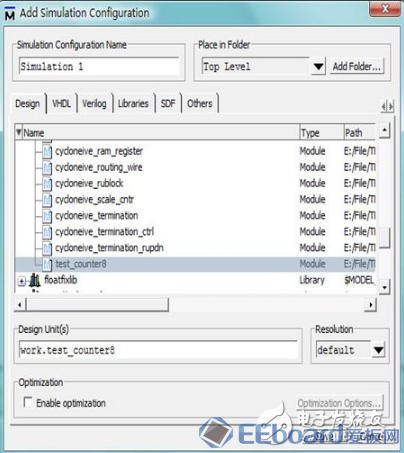
[color=rgb(34, 34, 34) !important]图7 Design选项卡的设置 [color=rgb(34, 34, 34) !important]
[color=rgb(34, 34, 34) !important]②再切换到“SDF”选项卡,点击“Add”添加“.sdo”文件,点击浏览后会直接出现这个“.sdo”文件的,选择即可,在下面的“Apply to Region”内输入“U”,这个就是我们的Test Bench程序中例化顶层文件的例化名字。如图8所示: [color=rgb(34, 34, 34) !important]
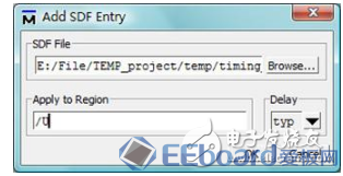
[color=rgb(34, 34, 34) !important] 图8 SDF选项卡的设置 [color=rgb(34, 34, 34) !important]
[color=rgb(34, 34, 34) !important]接着把下面的两个SDF选项的复选框都选中。如图9所示: [color=rgb(34, 34, 34) !important]
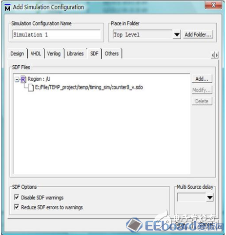
[color=rgb(34, 34, 34) !important] 图9 选中SDF选项的两个复选框 [color=rgb(34, 34, 34) !important]
[color=rgb(34, 34, 34) !important]点击“OK”退出配置设置界面。配置好了以后的Project区域的内容如图10所示: [color=rgb(34, 34, 34) !important]

[color=rgb(34, 34, 34) !important]图10 Project区域的内容 [color=rgb(34, 34, 34) !important]
[color=rgb(34, 34, 34) !important]7. 双击Simulation执行仿真,后面的步骤和功能仿真一样的了,不再赘述。仿真的波形图如图11所示: [color=rgb(34, 34, 34) !important]

[color=rgb(34, 34, 34) !important] 图11 时序仿真的波形图 [color=rgb(34, 34, 34) !important]
[color=rgb(34, 34, 34) !important]从图11中可以看到dout相对于主时钟clk有明显的延时,这个延时大小与当前使用的器件的时序模型有关。 [color=rgb(34, 34, 34) !important] 在具体实践过程中,可能还会遇到各种各样的问题,ModelSim正常运行也依赖于仿真库文件的齐备,所以碰到某些工程在仿真中遇到报错的情况时,不妨检查下ModelSim的提示信息,看看是否有仿真所必需的库文件没有添加进来。
[color=rgb(34, 34, 34) !important]来源 电子发烧友网
[color=rgb(34, 34, 34) !important]
[color=rgb(34, 34, 34) !important]
[color=rgb(34, 34, 34) !important]
|  /2
/2 
 /2
/2 